


Reverse Engineering Legacy Components With Modern Tools
The Imperative for Reverse Engineering Legacy Systems
The operational landscape of many manufacturing facilities is characterized by a significant investment in machinery that has been in service for years, if not decades. These legacy systems, while robust and reliable, often present unique challenges that can severely impact productivity and profitability. The most pressing issue is obsolescence: as technology advances, original equipment manufacturers (OEMs) frequently discontinue support, spare parts, and even the production lines for older components. This leaves manufacturers vulnerable to extended downtime when a critical part fails, as obtaining a replacement can become a prolonged and expensive endeavor, if not impossible.
Beyond obsolescence, the lack of comprehensive or accurate documentation poses another significant hurdle. Original drawings, specifications, or CAD models may have been lost, are incomplete, or were never digitized. Proprietary designs further complicate matters, as OEMs are often reluctant to share intellectual property, even for components that are no longer actively produced. Supply chain disruptions, exacerbated by global events, also highlight the fragility of relying on single-source suppliers for legacy parts. In such scenarios, the ability to independently reproduce or source replacement components becomes a strategic necessity.
The need for reverse engineering also extends to upgrading and optimizing existing machinery. Legacy components, while functional, may not meet modern performance, efficiency, or safety standards. By reverse engineering these parts, engineers can not only recreate them but also apply contemporary design principles, materials science, and manufacturing techniques to enhance their performance, reduce weight, improve durability, or integrate them into more advanced control systems. This proactive approach transforms a potential liability into an opportunity for innovation and competitive advantage.
Failing to address these challenges through reverse engineering can lead to significant financial repercussions. Prolonged downtime directly translates to lost production, missed deadlines, and contractual penalties. The cost of emergency repairs, often involving custom fabrication without proper documentation, can be exorbitant and yield suboptimal results. Moreover, the inability to upgrade or adapt legacy systems can hinder a company’s ability to adopt new processes, comply with evolving regulations, or compete effectively in a rapidly changing market. Therefore, for any forward-thinking manufacturing or industrial engineering operation, embracing modern reverse engineering is not merely an option but a critical component of a robust maintenance, repair, and operations (MRO) strategy, ensuring resilience and sustained productivity.
High-Precision 3D Scanning and Data Acquisition

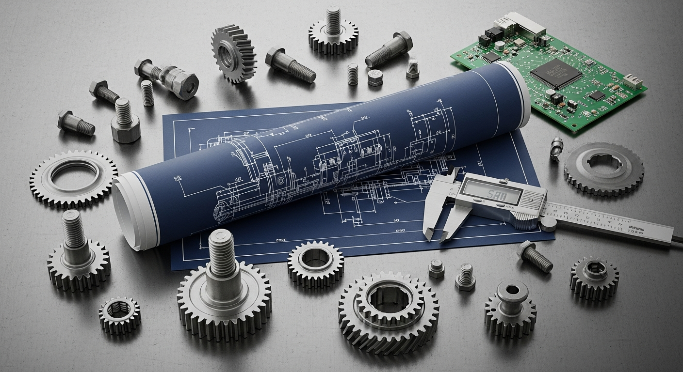
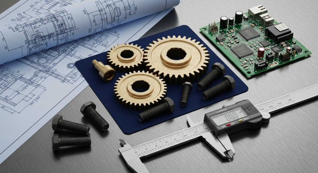
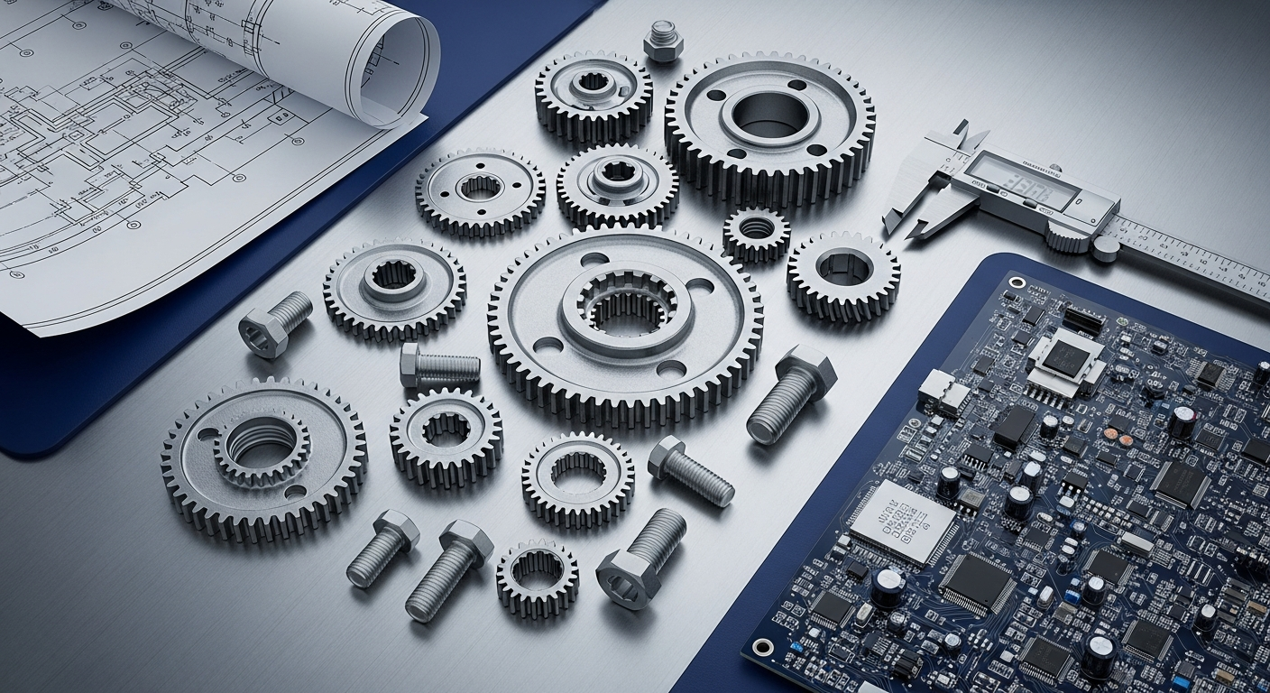
The foundation of any successful reverse engineering project lies in accurate and comprehensive data acquisition. Modern 3D scanning technologies have revolutionized this initial phase, transforming what was once a labor-intensive, manual measurement process into a fast, highly precise, and data-rich operation. These tools capture the physical geometry of a legacy component with incredible detail, generating a digital representation that serves as the blueprint for reconstruction.
Among the leading technologies, laser scanning stands out for its versatility and precision. Handheld laser scanners offer flexibility for capturing complex geometries and difficult-to-reach areas, often providing real-time feedback. Fixed or articulated arm CMM-based (Coordinate Measuring Machine) laser scanners deliver exceptional accuracy, ideal for critical dimensions and tight tolerances. Structured light scanners project patterns onto an object’s surface and capture the deformation with cameras, offering high resolution and speed, particularly effective for intricate details and organic shapes. The choice between these depends on the component’s size, material, required accuracy, and environmental conditions. For instance, reflective or transparent surfaces may require dulling sprays, while very large objects might benefit from photogrammetry, which stitches together multiple high-resolution images to create a 3D model.
For components with internal features, hidden cavities, or complex assemblies that cannot be disassembled without damage, industrial Computed Tomography (CT) scanning is indispensable. Similar to medical CT scans, industrial CT uses X-rays to generate cross-sectional images, which are then reconstructed into a full 3D volumetric model. This non-destructive technique allows engineers to visualize internal structures, identify material defects, measure wall thicknesses, and analyze intricate internal geometries without altering the original part. This capability is particularly crucial for complex castings, welded assemblies, or sealed components where internal dimensions and relationships are critical.
Practical considerations during data acquisition are paramount. Surface preparation, such as cleaning or applying matte spray, can significantly improve scan quality. Environmental factors like lighting, temperature, and vibrations must be controlled to maintain accuracy. The density of the point cloud—the collection of discrete data points captured by the scanner—is another key parameter. A higher density captures more detail but results in larger data files, requiring robust processing power. The output of these scanning processes is typically a point cloud, a raw dataset representing the component’s surface as millions of individual points. This raw data then requires specialized software for processing, noise reduction, and conversion into a usable mesh or surface model, paving the way for the digital reconstruction phase. The quality of this initial data acquisition directly determines the accuracy and reliability of the entire reverse engineering project, making the selection and skilled operation of these modern 3D scanning tools absolutely critical.
From Point Cloud to Parametric CAD: The Digital Reconstruction Phase
Once the physical component has been meticulously captured as a high-density point cloud or volumetric data, the next critical step in Reverse Engineering Legacy Components With Modern Tools is to transform this raw data into a functional, editable, and intelligent Computer-Aided Design (CAD) model. This digital reconstruction phase is where specialized reverse engineering software plays a pivotal role, translating millions of discrete data points into geometric features that engineers can manipulate and analyze.
The process typically begins with data clean-up. Raw scan data often contains noise, outliers, and redundant points that need to be filtered and refined. Following this, the point cloud is usually converted into a polygon mesh (e.g., STL format), which provides a surface representation of the object. This mesh is then the primary input for feature extraction. Modern reverse engineering software, such as Geomagic Design X, PolyWorks Inspector, or specialized modules within leading CAD packages like SOLIDWORKS or Inventor, employs sophisticated algorithms to identify and reconstruct geometric primitives. This includes recognizing planes, cylinders, cones, spheres, and fillets from the mesh data. For organic or freeform surfaces that cannot be described by simple mathematical equations, the software uses advanced surfacing techniques like NURBS (Non-Uniform Rational B-Splines) to create smooth, accurate surface patches that precisely conform to the mesh.
A key distinction in this phase is the goal: mere replication versus design intent reconstruction. While some projects may only require an exact digital twin (a “dumb solid” or surface model), many reverse engineering efforts aim to create a parametric CAD model. A parametric model incorporates design intent, meaning features are defined by parameters (dimensions, relationships, constraints) that can be easily modified. This allows engineers to not only recreate the part but also to understand its design logic, make modifications, and optimize it. Reconstructing design intent involves identifying patterns, symmetry, and functional relationships between features, and then building the CAD model using traditional CAD sketching and feature creation tools, often “snapping” to the underlying mesh data for accuracy.
The output of this phase is a clean, fully editable CAD model, typically saved in standard exchange formats like STEP or IGES, or directly in native CAD formats. This model is dimensionally accurate, reflecting the physical component, and can be used for a multitude of downstream applications: manufacturing new parts, performing engineering analysis, creating technical drawings, or integrating into larger assemblies. The transition from raw scan data to an intelligent parametric CAD model is a testament to the power of modern software, enabling manufacturers to not only digitally archive their legacy assets but also to unlock their potential for future innovation and operational resilience.
Advanced Simulation and Analysis for Re-engineered Components
Once a legacy component has been successfully reverse-engineered into a high-fidelity CAD model, the journey doesn’t end with mere replication. Modern tools enable engineers to subject these digital models to rigorous simulation and analysis, validating their design, predicting performance under various conditions, and identifying opportunities for optimization before any physical material is cut. This proactive approach is a cornerstone of industrial engineering and significantly mitigates risks associated with manufacturing new or modified components.
Finite Element Analysis (FEA) is perhaps the most widely used simulation technique. By dividing the CAD model into a mesh of discrete elements, FEA software can predict how a component will behave under different loads, stresses, and environmental conditions. For re-engineered parts, this is crucial for verifying structural integrity, assessing fatigue life, identifying stress concentrations, and ensuring the part meets or exceeds original performance specifications, especially if material changes or design modifications are considered. For example, an engineer can simulate the forces experienced by a gearbox housing or a machine frame, ensuring the re-designed part can withstand operational stresses over its expected lifespan without premature failure.
Computational Fluid Dynamics (CFD) is another powerful tool, particularly relevant for components involved in fluid flow or heat transfer. If a legacy component is part of a pump, valve, heat exchanger, or any system where fluid dynamics play a role, CFD can analyze flow rates, pressure drops, heat dissipation, and potential turbulence. This allows for optimization of internal passages, cooling channels, or aerodynamic profiles, potentially improving the efficiency and performance of the re-engineered part beyond its original design. For instance, optimizing the internal geometry of an old manifold can lead to significant energy savings.
Beyond static and fluid analyses, kinematic and dynamic simulations are vital for re-engineered components that are part of moving assemblies. These simulations can predict the motion, forces, and interactions between multiple parts in a system, ensuring proper fit, function, and avoiding interference. This is invaluable for complex mechanisms like robotic arms, cam-follower systems, or intricate linkages within manufacturing machinery. Furthermore, advanced techniques like topology optimization can be applied to re-engineered models. This generative design approach, guided by specified loads and constraints, can autonomously suggest optimal material distribution, often resulting in lighter, stronger, and more efficient designs than the original, pushing the boundaries of what was possible with traditional manufacturing.
The benefits of integrating advanced simulation into the reverse engineering workflow are profound: it reduces the need for expensive physical prototyping and iterative testing, accelerates the design validation cycle, lowers the risk of costly manufacturing errors, and ultimately leads to more reliable and higher-performing replacement parts. By predicting performance digitally, manufacturers can ensure that their re-engineered legacy components are not just replicas, but often significant improvements, seamlessly integrating into and enhancing modern manufacturing operations.
Additive Manufacturing and Rapid Prototyping in Reverse Engineering Workflows
The advent of additive manufacturing (AM), commonly known as 3D printing, has been a game-changer in the world of industrial engineering, particularly within the workflow of Reverse Engineering Legacy Components With Modern Tools. Once a legacy component has been digitally reconstructed into a precise CAD model, additive manufacturing provides an unparalleled capability to rapidly prototype, test, and even directly produce replacement parts, dramatically shortening lead times and overcoming the limitations of traditional manufacturing methods.
Rapid prototyping is one of the most immediate and impactful applications. Before committing to expensive tooling or large-scale production, engineers can 3D print functional prototypes of the re-engineered component. This allows for quick iteration and physical validation of fit, form, and function. A prototype can be installed into an assembly to check for interferences, tested for basic mechanical properties, or evaluated for ergonomic considerations. This iterative process, enabled by AM, significantly reduces the risk of design flaws making it to final production, saving considerable time and cost. For example, a plastic prototype of a complex bracket or housing can confirm mounting points and clearances within hours or days, rather than weeks for a machined part.
Beyond prototyping, additive manufacturing is increasingly used for the direct production of replacement parts, especially for obsolete components or those required in low volumes. For legacy machinery, where only one or a few replacement parts are needed, traditional methods like casting or machining can be prohibitively expensive due to tooling costs and setup times. 3D printing, however, can produce these parts on demand, directly from the CAD model, eliminating the need for specialized tooling. This “digital spare parts” strategy provides unparalleled agility in maintaining older equipment, minimizing downtime, and extending the operational life of valuable assets.
The choice of additive manufacturing technology depends on the material requirements and desired mechanical properties. For polymer-based components, technologies like Fused Deposition Modeling (FDM), Stereolithography (SLA), or Selective Laser Sintering (SLS) can produce parts with varying strengths, flexibilities, and surface finishes. For metallic legacy components, advanced processes like Selective Laser Melting (SLM), Direct Metal Laser Sintering (DMLS), or Binder Jetting can produce functional metal parts with mechanical properties comparable to traditionally manufactured components. This allows manufacturers to recreate complex metal geometries, such as impellers, turbine blades, or specialized fixtures, that would be difficult or impossible to produce with conventional machining or casting.
Considerations for using AM include material properties, post-processing requirements (e.g., heat treatment, surface finishing), and cost-effectiveness for different production volumes. While AM excels at low-volume, high-complexity parts, it may not always be the most economical choice for high-volume production of simple geometries. However, its ability to bypass tooling, enable rapid customization, and produce intricate designs makes it an indispensable tool in the modern reverse engineering toolkit, ensuring that manufacturers can keep their legacy systems running efficiently and effectively.
Data Management, Collaboration, and Ensuring Compliance
While advanced tools for scanning, modeling, simulation, and manufacturing form the technical backbone of Reverse Engineering Legacy Components With Modern Tools, the success and sustainability of these efforts critically depend on robust data management, seamless collaboration, and strict adherence to compliance standards. Without these organizational pillars, even the most technologically sophisticated reverse engineering project can fall short of its potential or introduce new risks.
Effective data management is paramount. Reverse engineering generates vast amounts of data, from raw point clouds and mesh models to parametric CAD files, simulation results, manufacturing instructions, and quality inspection reports. A Product Lifecycle Management (PLM) system becomes indispensable for managing this digital footprint. A PLM system provides a centralized repository for all reverse-engineered data, ensuring version control, traceability, and secure access. It allows engineers to track the evolution of a component from initial scan to final production, manage change orders, and maintain a complete audit trail. This is crucial for preventing data loss, ensuring data integrity, and providing a single source of truth for all stakeholders. Proper data management also facilitates the long-term archiving of reverse-engineered assets, creating a valuable digital library that can be leveraged for future maintenance or upgrade projects.
Collaboration is another key factor. Reverse engineering projects are inherently multi-disciplinary, involving specialists from design, mechanical engineering, materials science, manufacturing, and quality assurance. Modern collaboration platforms, often integrated within PLM or CAD environments, enable these diverse teams to work together efficiently, regardless of their geographical location. Features such as shared workspaces, real-time annotation, design review tools, and automated notifications streamline communication and decision-making. This ensures that insights from one discipline (e.g., a material expert identifying a better alloy) can be quickly integrated into the design and manufacturing process, leading to superior outcomes.
Ensuring compliance is a non-negotiable aspect of reverse engineering, particularly in regulated industries like aerospace, medical devices, or automotive. This encompasses several dimensions: regulatory standards (e.g., ISO, ASME, industry-specific certifications), quality control, and intellectual property (IP) considerations. Manufacturers must ensure that re-engineered components meet all relevant safety, performance, and environmental standards. This often involves rigorous testing, documentation of materials and processes, and adherence to quality management systems. Furthermore, while reverse engineering for maintenance, repair, or interoperability is generally permissible, it is crucial to navigate intellectual property laws carefully. The intent and use of the re-engineered part must be clearly defined to avoid infringement. Legal counsel should be consulted to establish clear guidelines and ensure all activities comply with relevant patent, copyright, and trademark laws.
By investing in robust data management systems, fostering a collaborative environment, and maintaining a steadfast commitment to compliance, manufacturers can transform reverse engineering from a reactive problem-solving activity into a strategic capability. These organizational frameworks ensure that the technical prowess of modern tools is fully leveraged, providing a secure, efficient, and legally sound pathway to maintaining and enhancing legacy manufacturing operations.
Comparison Table: Modern Reverse Engineering Methods & Tools
| Method/Tool/System | Key Application | Advantages | Disadvantages/Considerations |
|---|---|---|---|
| Laser Scanners (Handheld, CMM-based, Structured Light) | External geometry capture, high precision surface data. | High accuracy (micron level), fast data acquisition, versatile for various sizes/geometries. | Can struggle with reflective/transparent surfaces, line-of-sight limitations, large data files. |
| Industrial CT Scanning | Internal geometry capture, non-destructive inspection, material defect analysis. | Captures hidden features without disassembly, provides volumetric data, material analysis. | High cost, slower than surface scanning, limited by component size/material density, radiation safety. |
| Reverse Engineering Software (e.g., Geomagic Design X, PolyWorks) | Point cloud to parametric CAD conversion, feature recognition, surfacing. | Transforms raw data into editable models, reconstructs design intent, enables modifications. | Steep learning curve, high software cost, requires skilled operators, time-intensive for complex parts. |
| FEA/CFD Simulation Software (e.g., ANSYS, Abaqus, SolidWorks Simulation) | Performance validation, stress analysis, fluid dynamics, thermal analysis, optimization. | Predicts real-world behavior, identifies design flaws early, reduces physical prototyping, optimizes performance. | Requires expert knowledge, significant computational resources, model simplification challenges, simulation accuracy depends on input data. |
| Additive Manufacturing (3D Printing – FDM, SLA, SLS, SLM, DMLS) | Rapid prototyping, low-volume production of obsolete parts, custom tooling. | Fast iteration, no tooling costs, geometric complexity freedom, on-demand manufacturing. | Material property limitations (compared to traditional methods), post-processing often required, higher cost per part for high volumes, build size limits. |
| Product Lifecycle Management (PLM) Systems | Data management, version control, collaboration, documentation. | Centralized data repository, ensures data integrity, facilitates multi-team collaboration, audit trails. | Complex implementation, high initial cost, requires organizational change management, ongoing maintenance. |